Key Takeaways
- Most disc spring failures trace back to five causes: hydrogen embrittlement, fatigue from over-deflection, wrong stacking configuration, corrosion from material mismatch, and poor installation.
- You can prevent most failures by verifying plating and bake-out processes, limiting dynamic deflection to 75% of cone height, confirming stack layout matches your load and travel needs, and inspecting bearing surfaces.
- Material selection matters as much as load calculation. Stainless steel and high-alloy options like Inconel protect against corrosion and temperature extremes.
- This article gives you practical checks and specific changes to apply on your next belleville disc spring project.
Introduction: Are Your Disc Springs Failing Early?
Are your disc springs or Belleville washers failing before their expected service life?
Manufacturers report that 30-40% of field returns fail at just 10-20% of design life. The causes are commonly diagnosable and preventable.
This article covers 5 specific failure causes that design engineers, maintenance engineers, and buyers encounter in real applications. Belleville disc springs are governed by the specifications outlined in the European DIN EN 16984/16983 standards, which were formerly known as DIN 2092/2093. These components are used across various industries, including automotive, aerospace, and energy, due to their ability to handle massive loads in tight spaces, and many engineers rely on custom and stock Belleville disc springs for diverse industrial applications to meet those requirements. The conical shape allows them to support high loads with relatively small deflections and solid heights compared to traditional helical springs.
Belleville disc springs provide very high forces in reduced spaces, making them ideal for applications requiring high load capacity with minimal deflection. They maintain constant tension in bolted assemblies, preventing loosening caused by vibration, thermal cycling, or material creep. Belleville springs are also employed in safety relief valves to ensure precise sealing and actuation pressure, and specialized Belleville springs and precision valve components are often used to reduce leaks and fugitive emissions in these assemblies.
Each cause below includes what it is, how it shows up in the field, what to inspect, and what to change.
Cause 1: Hydrogen Embrittlement in Disc Springs
Hydrogen embrittlement disc spring failure occurs when atomic hydrogen enters the steel lattice during electroplating, pickling, or acid cleaning. The hydrogen concentrates in high-strength spring steel structures, reducing ductility.
This affects disc springs made from alloys like 6150 or 1074, especially above 40 HRC hardness. Hydrogen lowers cohesive strength at grain boundaries, causing sudden brittle fracture at stresses 20-50% below yield.
How it shows up:
- Sudden fracture at 10-30% of design load
- Cracking within days or weeks after installation
- Clean granular fracture surfaces, often at the ID edge
- No plastic deformation visible
What to check:
- Plating method used (electroplating vs. mechanical zinc)
- Post-plate bake-out time and temperature
- Compliance with ASTM B633 or equivalent specifications
- Material hardness range (HRC 40-50 is high risk)
What to change:
- Specify mechanical zinc or zinc flake coatings instead of electroplating
- Require bake-out documentation showing 190-230°C for 4-23 hours
- Ask about alternative coatings for springs above 40 HRC
A stack of 25mm OD belleville discs in an oilfield bolt fractured 24 hours after zinc plating. The supplier had omitted the required 200°C/12h bake-out. After adding the bake-out step and switching to flake coating, the manufacturer reported zero failures in a 500-unit follow-up, illustrating the value of working with a supplier that offers proven high-temperature, cryogenic, and downhole drilling spring solutions.
Did your supplier provide heat treatment and bake-out documentation with your last disc spring order?
Cause 2: Fatigue Failure from Over-Deflection
Disc spring fatigue life drops when repeated cycles exceed design deflection limits. The load-deflection curve becomes critical in dynamic service.
Static applications like bolted flange preloads see fewer than 1000 cycles over their life. Dynamic applications like downhole tools or stamping presses may reach millions of cycles. In oil and gas service, Belleville washers and springs for drilling and refining applications are specifically engineered to withstand these demanding dynamic loads. Belleville springs exhibit a non-linear load-deflection curve, complicating force calculation and prediction for high-cycle service.
The deflection of disc springs in a series stack is not directly proportional to the number of springs due to a bottoming out effect when compressed beyond 95%.
How it shows up:
- Cracks starting at the inner diameter edge
- Micro-cracks at the top contact surface
- Complete separation of the conical section after 20-50% of expected life
What to check:
- Working deflection as percentage of free cone height
- Stroke per cycle and total cycle count from data logs
- Whether the spring was designed for static or dynamic use
Design rules:
- Keep working deflection within 75% of cone height for cycling applications
- Higher deflection (up to 100%) suits static loading only
- Add springs in series to spread total stroke across multiple springs
A stack in a 10 Hz stamping press reaches 1 million cycles in about 28 hours. At 83% deflection, fatigue life drops to 500,000 cycles versus 2 million cycles at 67% deflection.
Have you mapped your real in-service deflection against the published load-deflection curve?
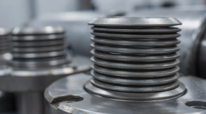
Cause 3: Improper Belleville Disc Spring Stacking Configuration
Belleville spring stacking configuration determines whether you get more load, more travel, or both. Disc springs can be stacked in series, parallel, or mixed combinations to achieve different load curves, including regressive, linear, or progressive characteristics.
What goes wrong:
- Springs bottom out when parallel stacks are used for deflection needs
- Loads fall short when series stacks are used for load requirements
- Uneven contact causes edge wear and hysteresis
Parallel stacking increases load capacity while maintaining the deflection of a single washer. Multiple springs nested in the same direction multiply force but not travel. Series stacking increases deflection while maintaining the load of a single washer.
Stacks of belleville springs are inherently self-damping due to friction between the surfaces, making them excellent for absorbing shocks. In a parallel stack, hysteresis losses occur due to friction, which can be beneficial for damping and vibration energy dissipation.
What to check:
- Does your design need more load or more travel?
- Is the current stack series or parallel?
- Look for polished flats indicating bottoming
Mixed stack guidance:
Combination stacking allows for highly specific, non-linear spring rates. A 3-3-2 pattern (two parallel-3 groups in series) yields load = 3× single and deflection = 2× single.
| Configuration | Load Result | Deflection Result |
| Parallel (same direction) | n × single | Same as single |
| Series | Same as single | n × single |
| 3-3-2 compound | 3 × single | 2 × single |
| Apply lubricant between discs in high-load stacks to reduce friction. DIN 2093 limits friction coefficient to μ<0.1 with proper lubrication. |
Have you measured the actual load curve of your stack and compared it with the theoretical calculation?
Cause 4: Corrosion and Wrong Disc Spring Material Selection
Disc spring material selection corrosion failures happen when pits from chlorides, H2S, or moisture create stress risers. These pits accelerate fatigue by 10-100× through crack initiation at high-stress zones near the ID and OD.
How it shows up:
- Surface rust and pitting
- Discoloration and force loss of 15-30%
- Transgranular cracks originating from pits
What to check:
- Is carbon steel (1075, 1095, 51CrV4) specified for wet or chemical service?
- Does operating temperature exceed the alloy’s rated range?
- Does your environment involve H2S requiring NACE MR0175 compliance?
Material options by environment:
| Environment | Recommended Materials |
| Wet/mildly corrosive | 300 series stainless steel |
| High strength + corrosion resistant | 17-4PH or 17-7PH stainless |
| High temperature (to 650°C) | Inconel 718, Inconel X-750 |
| Cryogenic | Elgiloy or similar alloys |
| The material selection for disc springs can accommodate working temperatures ranging from -400°F to 1100°F, as well as various corrosive environments and magnetism requirements, according to industry standards. |
Carbon steel offers 20-30% higher loads than stainless for the same geometry but requires coatings in moist conditions. Match your alloy to temperature range, fluid chemistry, and required life, leveraging Belleville washers and disc springs for industrial and heavy equipment solutions when you need engineered material choices. Request full heat traceability and EN 10204 3.1 certificates from manufacturers.
When did you last review your disc spring material spec against actual operating conditions?
Cause 5: Incorrect Installation and Bearing Surface Condition
Disc spring installation failure results from poor fit, wrong orientation, and inadequate bearing surfaces rather than the spring design itself. Even a well-designed belleville washer fails fast if the housing, guide rod, or flange surface is out of tolerance.
Belleville springs distribute loads uniformly around their circumference, reducing stress concentrations only when installed correctly.
Field symptoms:
- Uneven wear marks on ID or OD edges
- Galling on guide rods
- Stack tilting and inconsistent preload values
What to check:
- Guide rod or bore clearance (DIN 2093 specifies 0.1-0.3mm rod-ID, 0.2-0.5mm bore-OD)
- Bearing face flatness (within 0.01mm)
- Correct disc orientation relative to load direction
For disc springs with a thickness of more than 6.0mm, DIN 2093 specifies small contact surfaces at points where the load is applied and where the load touches the ground, which helps reduce friction and improve load application definition.
Use molybdenum disulfide paste (μ=0.05) for dynamic stacks. Specify Ra<0.8μm surface finish for all contact faces. In vehicles and industrial machinery, belleville springs provide the high, consistent force needed to engage or disengage mechanisms when properly installed.
One case involved a bolted joint where 0.05mm flange warp caused 30% ID overload and cracking within 1000 hours. Re-machining the bearing faces to 0.005mm flatness eliminated the issue.
Does your assembly procedure include a defined bearing surface inspection and orientation check step?
What To Do When a Disc Spring Fails
Do not replace a failed disc spring with an identical part without review.
First steps:
- Save the failed part for analysis
- Record where the crack or fracture started (ID, OD, or contact face)
- Photograph the stack and housing condition
Collect operating data:
- Load and deflection range
- Temperature and environment (dry, wet, chemical)
- Cycle rate and any shock load events
Match the failure appearance to the 5 causes listed above. Share the failed part and application data with your manufacturer for a design review. Update your specifications and assembly procedures once the root cause is confirmed, and consider engaging Belleville International’s engineering and contact team if you need support on redesign or failure analysis.
Why Work With a Specialist in Belleville Disc Springs
Disc springs and belleville washers are not generic flat washers. Small changes in thickness, cone height, or materials produce large load changes.
A dedicated manufacturer supports projects from concept to production with calculation support per DIN standards, fatigue estimates, and stacking configuration guidance, such as the family-owned Belleville International engineering and manufacturing group. Capabilities include custom dimensions, non-standard cone heights, special alloys including stainless steel and Inconel, and precision grinding of contact flats, which aligns with the comprehensive Belleville washers and disc spring manufacturing solutions offered by Belleville International.
When properly designed, belleville springs offer a very long service life and high fatigue resistance across a wide range of applications and fields, especially when they are engineered by a specialist Belleville International team with decades of experience.
Request a free engineering design review for your next disc spring application through our contact page.
FAQ
How long should a disc spring last in a dynamic application?
Fatigue life depends on deflection range, load level, material, surface finish, and environment. With correct design, many stacks reach 10⁵ to 10⁷ cycles. Request S-N curve data or fatigue test results from your supplier for your specific geometry. Validate life with a pilot test under real conditions before full production rollout.
When should I choose stainless steel disc springs instead of carbon steel?
Choose stainless steel when facing moisture, wash-down, salt, or mild chemicals. Common grades include 301, 302, or 17-7PH stainless. Carbon steel carries higher loads for the same size but needs coatings or controlled environments. Match alloy to your real-world environment first, then optimize load and dimensions with the manufacturer.
Can I mix different disc spring sizes or materials in one stack?
Mixing is technically possible but makes load-deflection behavior harder to predict. Mismatch in outside or inside diameters causes uneven loading, tilting, and stress concentrations. Keep all discs in a stack to the same size and material whenever possible. Involve your manufacturer if a mixed stack seems required so they can calculate and test it.
What tolerances matter most for disc spring installation?
Key tolerances include guide rod diameter relative to disc spring ID, housing bore relative to OD, bearing surface flatness, and perpendicularity between surfaces and guide axis. Too much clearance allows tilting and uneven wear. Too little causes jamming. Suggest using DIN 2093 as reference documents for recommended fits and tolerances when setting up new designs. Include these on production drawings for verification during assembly.
How do I know if my application is static or dynamic for disc spring design?
Static applications keep deflection and load nearly constant, with only small changes from thermal expansion. Dynamic applications move through noticeable stroke repeatedly each machine cycle or vibration event. If your disc spring sees thousands or more cycles during its life, treat it as dynamic. Share estimated cycles per day, stroke per cycle, and expected service years with your manufacturer to obtain the right fatigue life in accordance with your specifications.